Originally published on fastradius.com on January 27, 2021
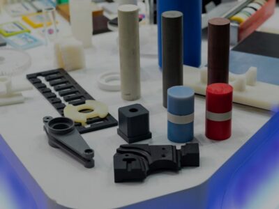
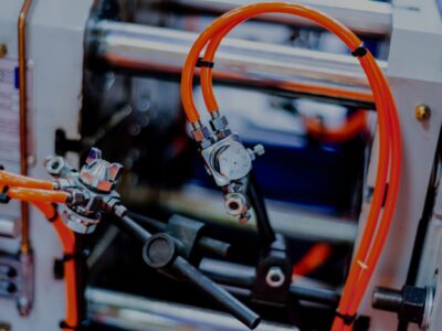
Injection molding enables high volume production of identical parts at a low price per part. The process involves injecting molten material into durable metal molds through a pressurized nozzle, ejecting the part once the material has set, and repeating. A wide range of everyday items, including water bottles, plastic toys, and electronics housings are made with injection molding. While thermoplastics and thermosets are the most common materials used in injection molding, metal can also be injection molded.
When you make a part with injection molding, you need to consider a number of variables that impact the quality and functionality of the final product. There are many ways an injection molded part can fail —including flow lines, sink marks, and warping — but you can avoid most problems by following a few key design principles.
Here at SyBridge, we work with customers on their injection-molded parts every day. Engineers often come to us with great part designs that need to be adjusted for before they can be made effectively. Our design for manufacturing (DFM) experts have evaluated and adjusted thousands of part designs, and they identified and compiled the most common issues they see. Fixing these common errors in your design can prevent costly mistakes and save a lot of time in design revisions.
Before you submit your part design to be injection molded, check it against this list of design rules:
Use appropriate draft angles
1.5-2 degrees of draft is typically a safe minimum for most parts.
Draft angles refer to the gentle taper added to the surfaces of an injection-molded part that align with the direction of pull, allowing the part to be removed from the mold without being damaged by friction or suction.
The required draft angle for a part depends on a few factors, including the wall thickness, the shrink rate of the part’s material, the depth of draw, and whether the part will require surface finishing or texturing during post-production. While the average draft should increase by 1 degree for each additional inch of part depth, 1.5-2 degrees of draft is typically a safe minimum for most parts.
Maintain uniform wall thickness, if possible
If possible, injection-molded components should have a uniform wall thickness throughout the entire part. Variations in wall thickness can cause the injected material to cool at different rates, which can lead to sink marks, voids, and warping.
Generally, wall thicknesses between 1.2mm and 3mm are ideal (though some variation can be expected depending on material). Wall thickness should almost always stay below 5mm because thicker walls increase production cycle times and may also negatively impact the mechanical properties of the part.
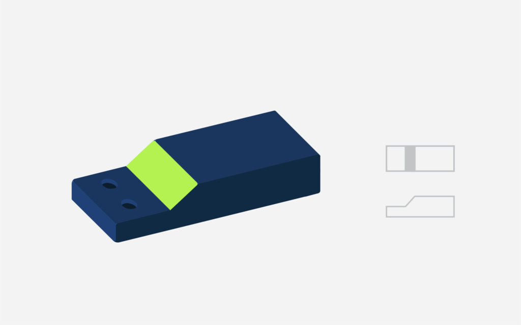
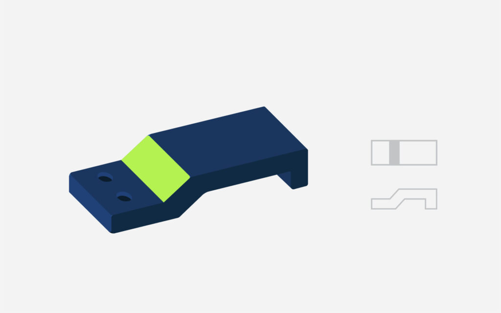
If a part requires variations in wall thickness, then you should make the transition between sections as gradual as possible. You can do this by incorporating chamfers (sloped corners or edges) or fillets (rounded corners or edges) into the part design, which help ensure that the shot of molten plastic fully fills the mold, cools thoroughly and evenly, and prevents warping or non-uniform shrinkage.
As a general rule, the length of the transition between sections with differing wall thickness should be 3x the change in wall thickness (e.g., if wall thickness decreases by 1mm, the transition should happen across 3mm).
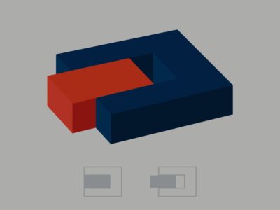
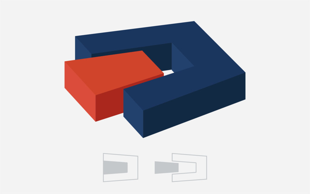
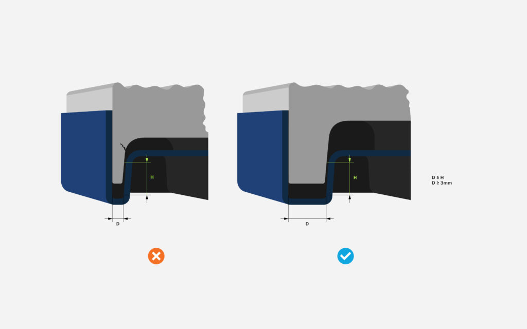
Avoid undercuts
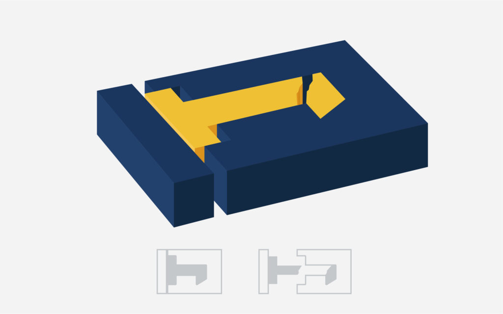
Undercuts are recessed or overhanging surfaces or features — such as threads, grooves, or snap-fits — that prevent a part from being ejected from the mold with a single, unidirectional pull without damage. It’s possible to avoid undercuts either by orienting features parallel to the draw line or by incorporating actions into your mold design.
Round out sharp edges and corners
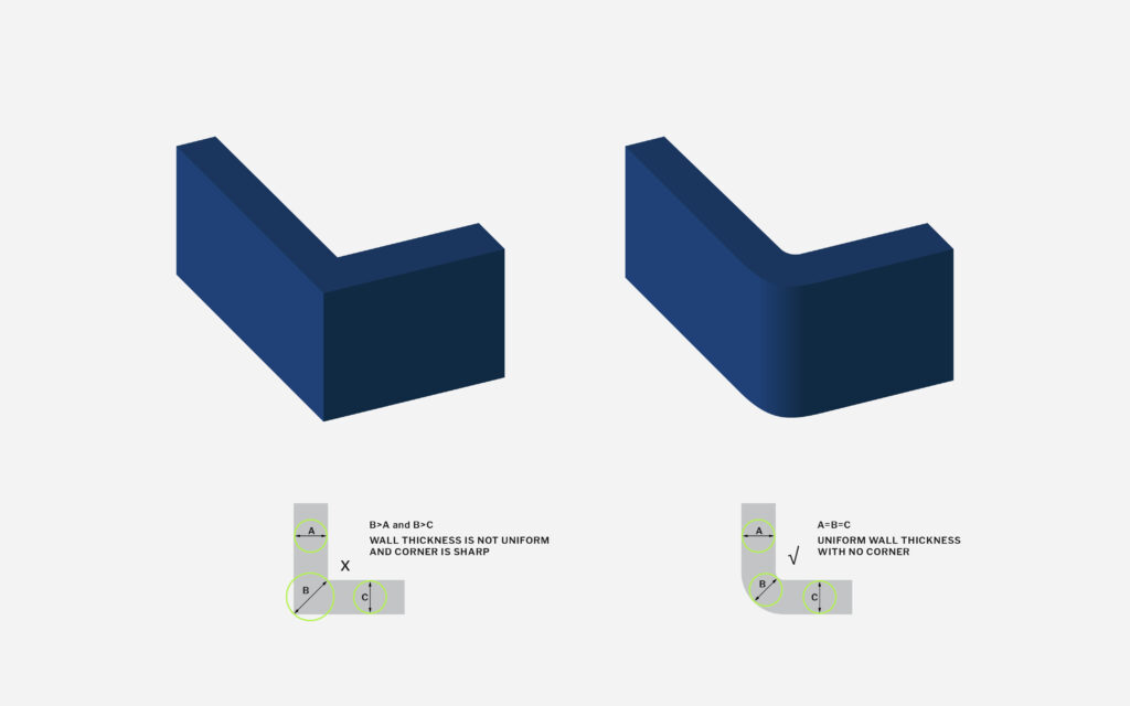
Whenever possible, designers and engineers should opt for round features instead of sharp edges and corners. Edges require additional pressure to fill, which makes it harder for a shot to efficiently and uniformly flow into the mold. Sharp edges also have a tendency to cling to the mold during ejection, increasing the risk of part damage and defects. You can avoid both these problems with radiused internal and external corners.
Internal corners, or those where part walls meet the floor, should have a radius of at least 50% the adjacent wall thickness. External corners, or those at the top of part walls, should have a radius of 150% the adjacent wall to allow plastic to flow more efficiently and effectively. This also helps minimize residual stress and cracking.
The base of all vertical features within a part (such as bosses, ribs, or snap fits) must also be rounded. Boss radii should be 25% of the adjacent wall, with a minimum radius of 0.015” (or 0.381mm).
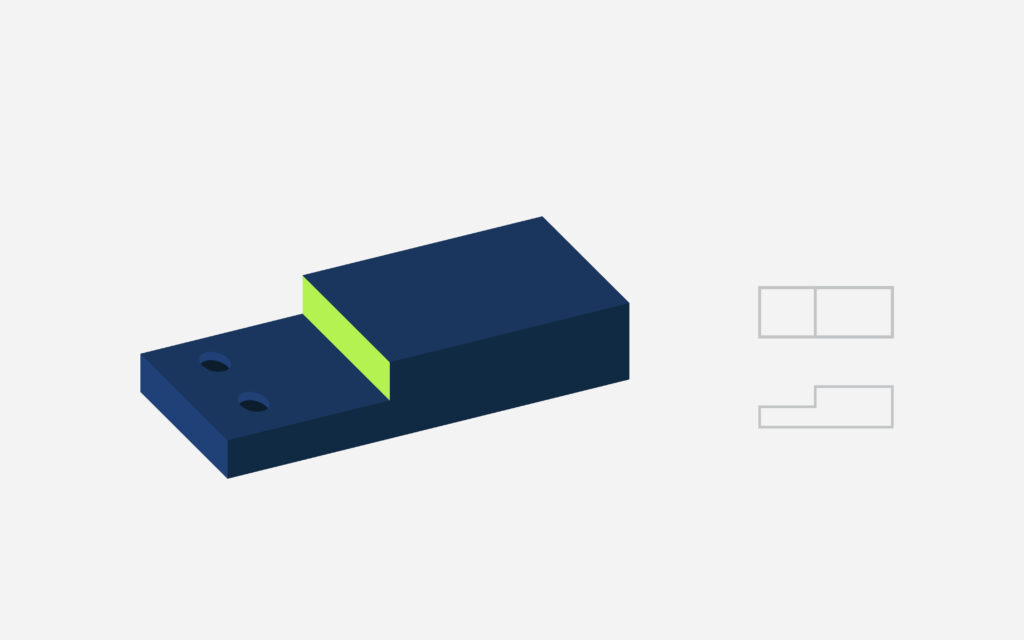
Situate parting lines strategically
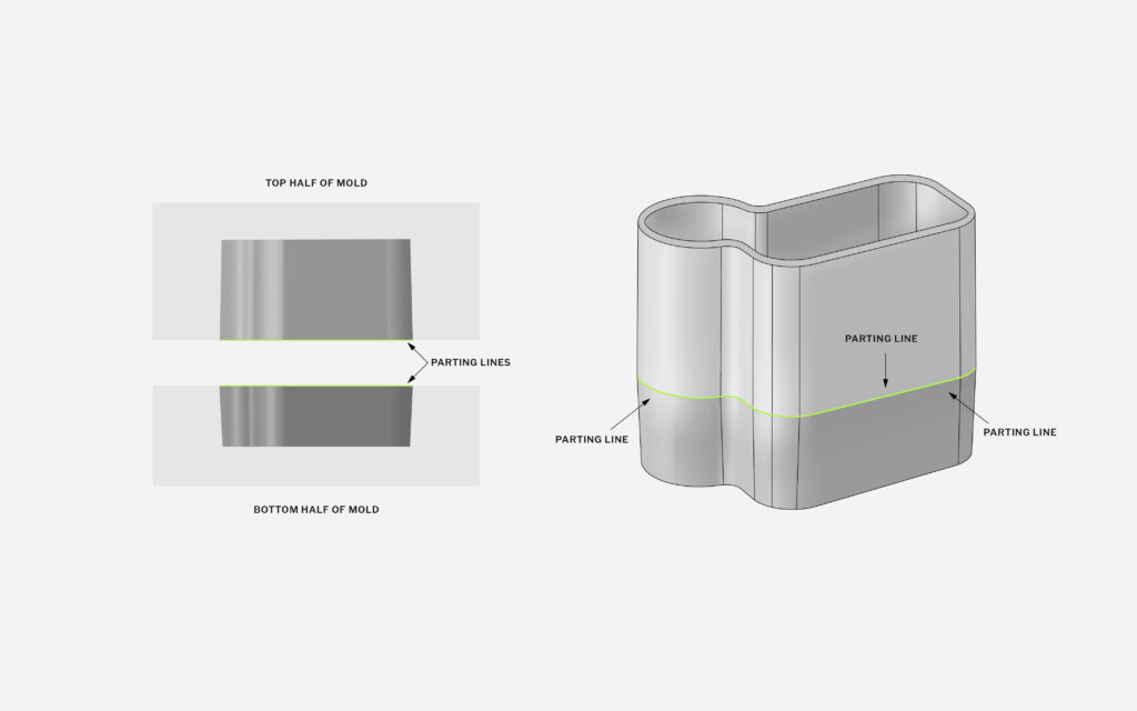
A physical mark, known as the parting line, will appear where the two halves of a mold meet. In many cases, parting lines can be easily seen and felt, but it’s more than an aesthetic issue. The placement of the parting line dictates how the mold opens (and therefore the direction in which you need to add draft to the part’s features), and it can influence both the cost of mold tooling and any required post-processing.
You can often improve a part’s appearance and functionality by placing the parting long along an edge rather than on a flat surface. This helps to hide the seam and also reduces the chances of flash (excessive material around where the mold comes together).
Consider ejector pin placement
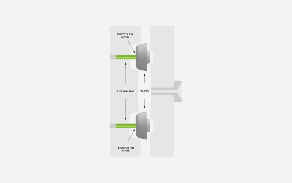
To work properly, ejector pins require flat surfaces, or pads, placed perpendicular to the direction of pin movement. The placement and number of pins should be informed by part shape, draft angles, sidewall texture, and wall depth — all of which influence how a part will cling to the mold walls.
Material choice should also be factored into the placement or size of pins. Stickier resins, for example, tend to require more force to eject. Likewise, softer plastics will likely need either a greater number of pins or wider pins in order to effectively distribute ejection force and avoid damaging the part.
Optimize the size of support ribs
Ribs are often used to strengthen part walls in situations where two part walls meet at a 90-degree angle, or where the length of a particular section is weakened by the section’s wall thickness.
It’s important to note that thicker ribs don’t necessarily mean greater support — in fact, ribs that are too thick often lead to sink marks. The base thickness of support ribs should be a maximum of two-thirds the thickness of the adjoining wall.
Be aware of mold wall thickness
The thickness of the mold’s walls is another important consideration — and one that will be primarily determined by the space between part features. Make sure that vertical features like ribs and bosses aren’t too close to each other, to part walls, or to thin areas, as this complicates the cooling process.
Mold wall thickness can also impact tooling costs. The majority injection molds are created through CNC machining and thinner walls of metal in the mold are more difficult to tool properly. Thinner walls also result in shorter mold life cycles.
While the minimum allowable mold wall thickness is dictated by the physical and mechanical qualities of the part material, a clearance of 3mm between part features is generally acceptable.
Designing injection-molded parts efficiently and effectively
Design mistakes are expensive. Re-cutting a tool to fix a design error could set product teams back weeks and cost thousands of dollars. A good manufacturing partner will help you avoid costly revisions with DFM, but that process adds to your timeline too. Checking your design for the issues in this guide before you submit it to a manufacturing partner will help you get better parts faster.
There are a lot of things that can go wrong in injection molding, so you need to find a partner you can trust to get your parts right. Here at SyBridge, we’re here to make things easier for you, and we’re invested in the success of your project. Contact us today to get started on your next injection molding project.